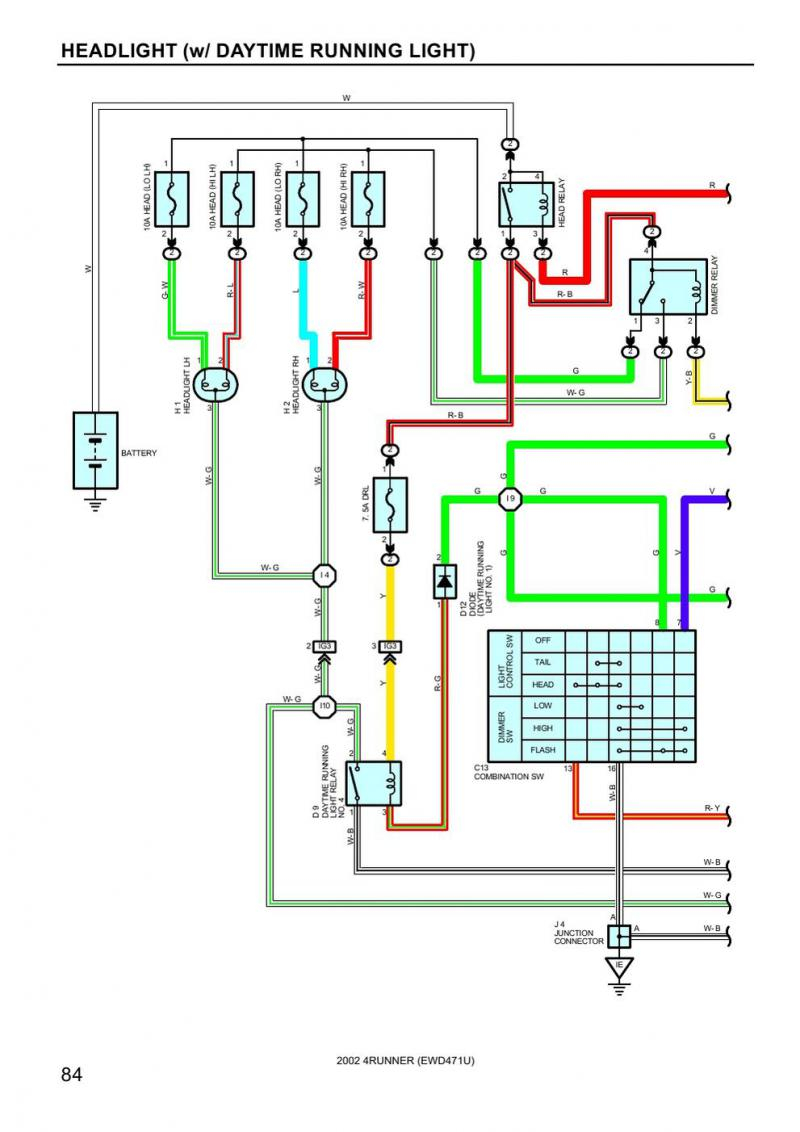
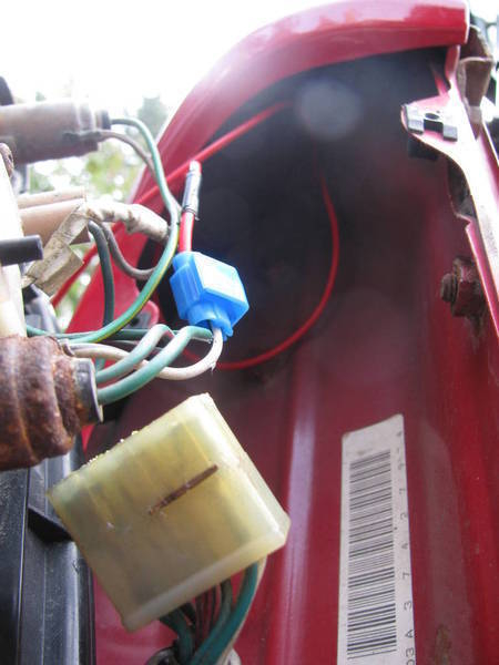
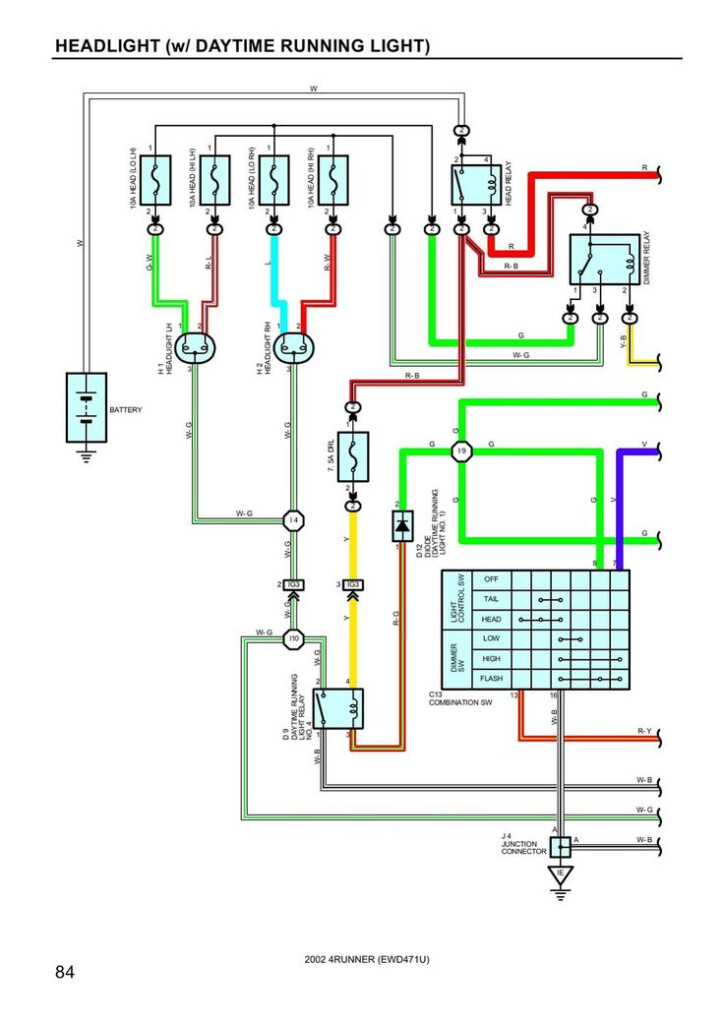
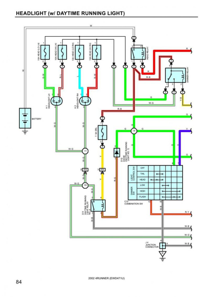
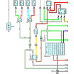
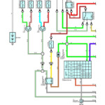
1996 Toyota Tacoma Brake Light Wiring Diagram – A cracked or dysfunctional tail light circuit could be the outcome of interior cabling difficulties with one particular or equally rear pods. Go across-cabling when you use low-common bulbs or aftermarket pods is most likely responsible for this. It’s also likely that the electrical wiring to the rear lamps was modified from a previous operator.
Locating the supply of a cabling concern is step one toward resolving it. Ensure that the place is corrosion-free and clean. Clean the ground place as essential, and change any rusted soil screws. Next, appear beneath the terrain screw for almost any more ring terminals. If this doesn’t fix the issue, try moving the harness’s ground wire to a new spot towards the bottom of the car.
difficulties with the correct (person area) light and the left (car owner area) lamp
The Toyota lights about the still left (vehicle driver side) and proper (traveler side) usually are not working properly. You have to initial establish the 2 bulbs’ power options. The correct change sign sign change powers the correct light, whilst the remaining turn sign indicator move powers the still left lamp. The steering column stalk management is linked to the left swap.
Check the fuse if you suspect a blown fuse. If it is bad, replace the fuse with one of the same amperage and size. If the fuse is functioning properly, remove the tail light cover to inspect the bulb. Some automobiles provide an entry solar panel in which the bulb is actually taken away.
A reduce relationship or possibly a very poor floor are two more prevalent brings about. Use a test lighting to attempt to identify the problem. A been unsuccessful indicator device is actually a further probability. Irregular hyperflashing can be a result of a malfunctioning signal device.
structural schematics for cabling
The electric powered support with your creating is designed and planned utilizing architectural electrical wiring schematics. In addition, they illustrate the areas of changes and lighting along with the contacts between the two. They may also have a story to help you read the signs, as well as showing in which the receptacles are.
Typically, electrical circuits are represented graphically in wiring diagrams. They display the general sizes and hues in the circuit’s constituent parts. They are also helpful for troubleshooting, as they illustrate the connections between components. They may be frequently used in electric assignments to assist personnel in locating and resolving issues.
