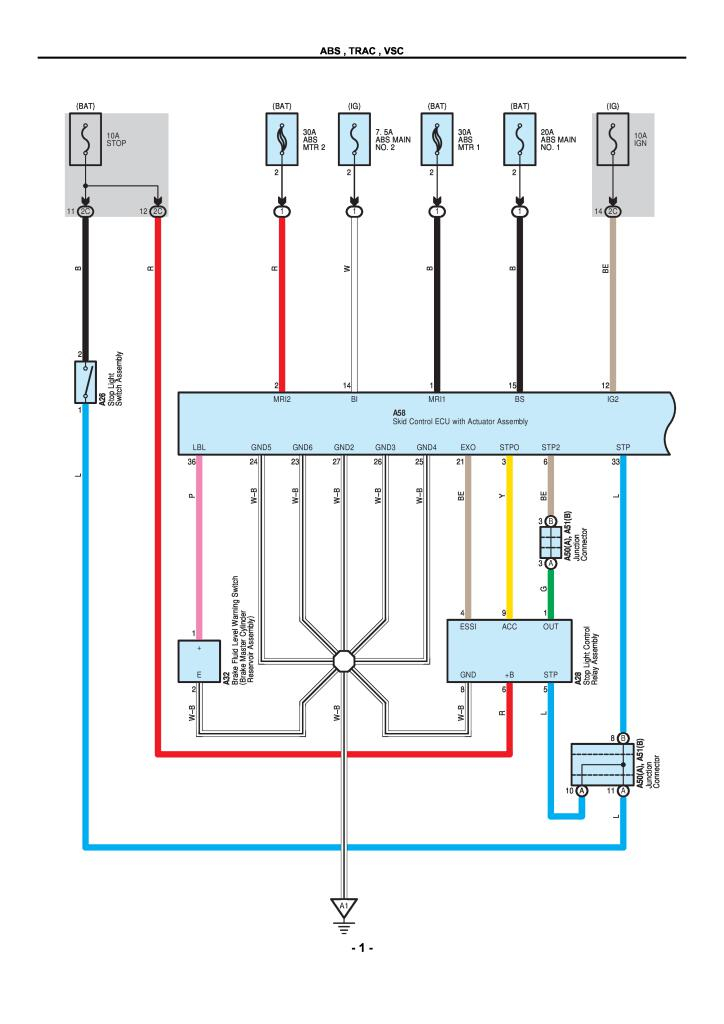
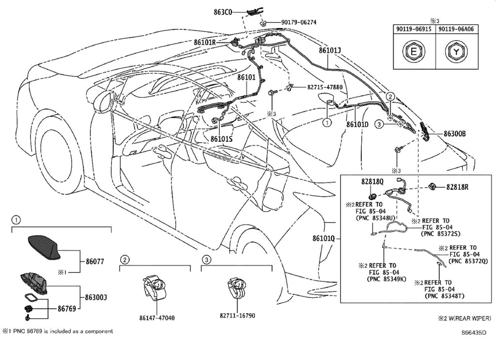
2002 Toyota Prius Electrical Wiring Diagram Pdf – The connector code is used to identify whether a connector is female or male. The computer code can also be employed to distinguish between various wire control designs. The male terminal connection is denoted by the icon (), while the men and women connector pin phone numbers are denoted by amounts outside of the rule.
The connections involving numerous pieces are exhibited from the wiring diagram. A link rule might be .5 or .3 mm, for example. Moreover mentioned is definitely the cable’s color code.
The pin quantities of equally male and female connectors are pointed out by phone numbers on the exterior of connector rules.
The locations and wire routings of the cabling harness are displayed within a wiring diagram. The very first message in the connection rule designates in which the connector is located on the diagram. An earth position is additionally incorporated around the schematic, which assists in figuring out the location where the connector ought to be located. In addition to earth mounting roles, the cabling diagram will even show the connectors and connector amounts that match exactly the same portion.
The wiring connector is not linked if there is no code. A damaged line furthermore signifies that the 2 connections are the exact same. It’s important to analyze a electrical wiring diagram carefully so you can right away establish the correct connector.
Floor absolutely nothing
The power link between a significant part and also the planet is known as the ground point. Around the Toyota electrical cabling schematic, the floor position rule is depicted by way of a message and a variety. The quantity denotes the earth point’s serial variety, as the message denotes the alphabetical code for your wire control. The ground position code also demonstrates the location where the ignition key and wire splice position are situated.
It helps to understand the different circuits in the car before starting to diagnose an electrical problem. A wires diagram shows the actual cabling of each circuit, which can be divided into a variety of circuits for each and every process within a motor vehicle. It is very important to learn how every circuit capabilities as well as the floor position that connects it.
prohibit connections for relays
In the still left aspect of the car’s instrument solar panel will be the relay prevent connections. They sign up for J/B No.3 towards the Tool Solar panel Cable (IW). 3 figures make up the program code on the relay prevent connectors, all of which appears for a particular wires or process. If the connector is male or female, additionally, it will say.
The diagram also displays the hue program code for that relay obstruct connector. The cable’s shade computer code is displayed in parenthesis within this diagram. Light blue will be the color designation for girl connections.
coded colours
Toyota electric cabling diagrams are color coded to produce medical diagnosis and trouble shooting less difficult. The corresponding shade requirements make it easier to establish the proper connection between various auto components. A electrical wiring utilize for Toyota autos includes numerous wires, including good and bad, soil, and/very low voltage wire connections. You ought to pay close attention to the natural/white and green/red-colored shades inside the electrical wiring schematic when reading it simply because they represent the still left change indicate and also the braking system lighting, correspondingly.
A Toyota Electronic Electrical wiring Diagram with red arrows suggests that the connections are definitely the suitable sizing. But be cautious about the yellow arrows. They are certainly not a reliable gauge from the right dimension. They may perplex you.
Toyota electrical wires diagram troubleshooting
Being familiar with your Toyota’s electric powered wires is crucial, specially the coloration requirements. Globally described Toyota electrical wiring color regulations may help in a quick diagnosis of electrical concerns. Because Toyota automobiles feature a large number of sensors and electrical components, it is crucial to comprehend the wiring diagram’s color codes.
The contacts involving significant components and ground points are displayed on the cabling diagram. The Instrument Panel Wire is coupled to the Motor Space Primary Cable by the “Ch1” connector (woman). On the still left kick panel, there is a connector. The middle of your back panel is when the “H2” ground stage is located. The link in between these areas and the other significant elements is revealed through the circuit diagram. Confirm the links to make certain that every single element is connected to the suitable soil.
