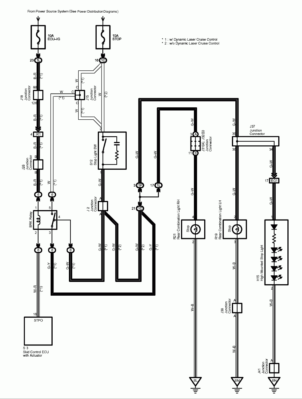
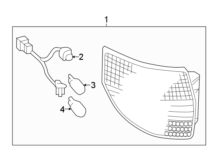
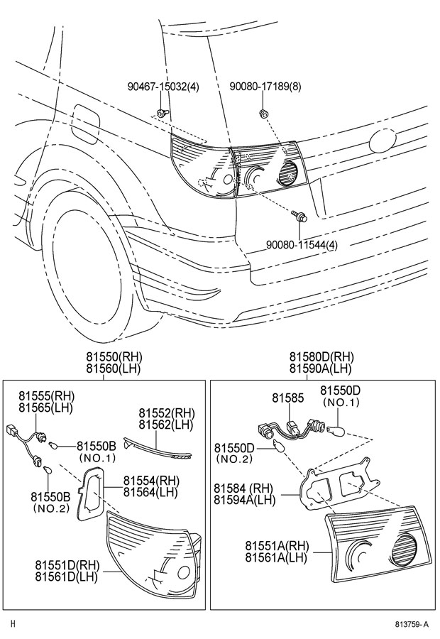
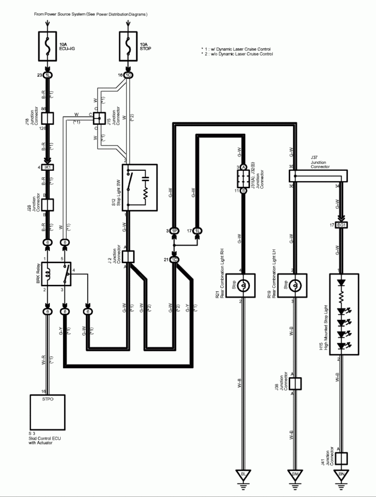
2005 Toyota Sienna Tail Light Wiring Diagram – A broken or dysfunctional tail lighting circuit can be the outcome of interior wiring difficulties with one particular or both back pods. Go across-wires when utilizing no-regular lamps or upgraded coffee pods is most likely to blame for this. It’s also possible that the wiring to the rear lamps was modified from a prior owner.
Choosing the way to obtain a cabling issue is the initial step toward solving it. Ensure that the region is corrosion-free and clean. Clear the soil area as necessary, and replace any rusted terrain screws. After that, appear below the soil attach for virtually any much more ring terminals. Try moving the harness’s ground wire to a new spot towards the bottom of the car if this doesn’t fix the issue.
difficulties with the proper (person part) light fixture as well as the left (driver part) light
The Toyota lamps around the kept (vehicle driver area) and proper (person part) usually are not working properly. You must initially ascertain the two bulbs’ potential options. The best change indicate sign change powers the right light, whilst the still left change transmission sign switch abilities the still left light. The directing line stalk manage is connected to the left move.
If you suspect a blown fuse, check the fuse. Replace the fuse with one of the same amperage and size if it is bad. Remove the tail light cover to inspect the bulb if the fuse is functioning properly. Some automobiles come with an gain access to solar panel in which the light bulb is simply eliminated.
A reduce connection or a bad floor are two more widespread brings about. Work with a examination light-weight to attempt to pinpoint the situation. A failed indicator model can be a additional likelihood. Intermittent hyperflashing may be caused by a flawed indicator system.
structural schematics for wires
The electric powered service within your developing is planned and designed making use of architectural cabling schematics. Moreover, they display the spots of changes and lighting effects along with the connections between the two. They could also have a story to help you read the symbols, as well as showing where receptacles are.
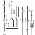
Electrical circuits are represented graphically in wiring diagrams, typically. They present the relative hues and sizes from the circuit’s constituent elements. As they illustrate the connections between components, they are also helpful for troubleshooting. They can be commonly used in electric projects to aid workers in resolving and locating problems.
