2012 Toyota Tacoma Electrical Wiring Diagram – The connector computer code is utilized to determine whether or not a connector is female or male. The code is also used to distinguish between various wire harness layouts. The guy terminal connection is denoted with the sign (), even though the female and male connector pin figures are denoted by figures away from computer code.
The links among different pieces are revealed with the wiring diagram. A link program code can be .5 or .3 millimeters, for example. Moreover stated may be the cable’s coloration code.
The pin variety of equally male and female connections are mentioned by phone numbers externally of connector rules.
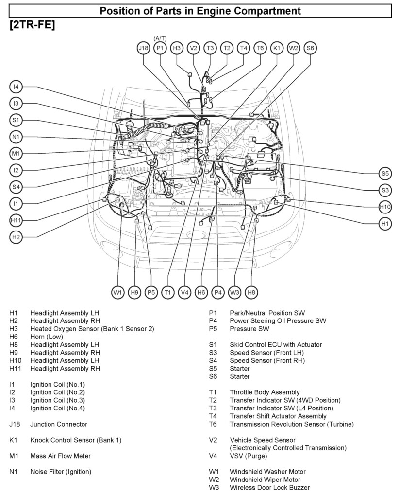
The wire and locations routings of your electrical wiring utilize are exhibited in the wiring diagram. The 1st letter of your interconnection code designates in which the connector is on the diagram. An the planet point is likewise incorporated in the schematic, which assists in identifying where connector should be put. Together with world mounting positions, the cabling diagram will even display the connectors and connector numbers that match the same portion.
If there is no code, the wiring connector is not linked. A broken line in addition suggests that the 2 connectors are similar. It’s important to take a look at a cabling diagram attentively in order to quickly determine the correct connector.
Ground absolutely nothing
The electrical connection between an important part and the world is called the soil position. In the Toyota electric powered wiring schematic, the earth level code is depicted with a letter plus a quantity. The telephone number denotes the earth point’s serial quantity, even though the notice denotes the alphabetical computer code for the wire control. The earth level program code also reveals the location where the ignition crucial and wire splice position are located.
Before starting to diagnose an electrical problem, it helps to understand the different circuits in the car. A electrical wiring diagram demonstrates the particular cabling for each circuit, which is split up into numerous circuits for every single process inside a car. It is crucial to know how each circuit capabilities as well as the terrain stage that joins it.
prevent connections for relays
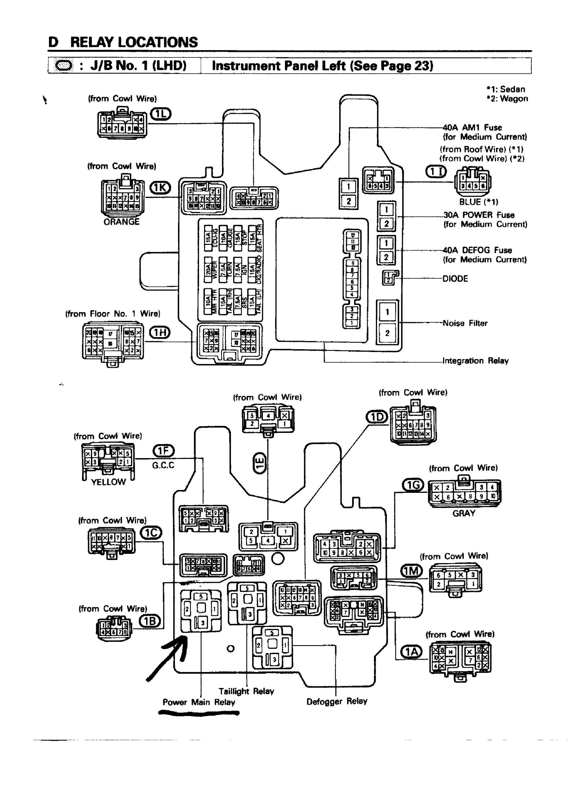
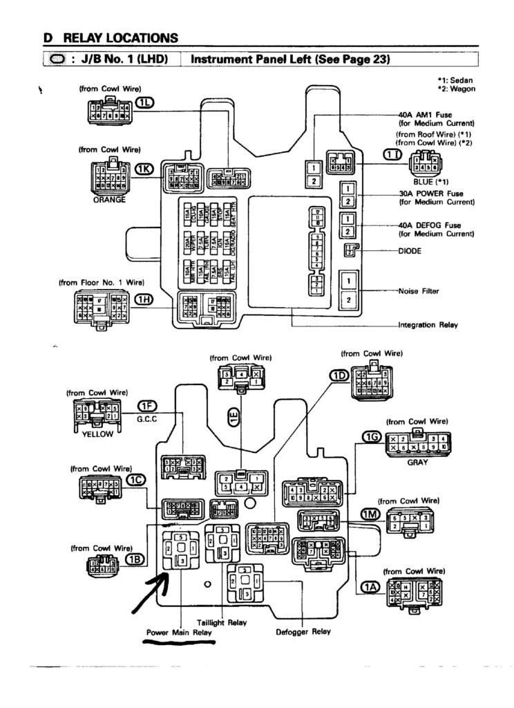
On the still left area of the car’s device solar panel are the relay obstruct connectors. They join J/B No.3 towards the Device Solar panel Wire (IW). A few characters constitute the computer code on the relay prohibit connections, all of which appears for the wiring or process. Additionally, it will say if the connector is male or female.
The diagram also demonstrates the color computer code for the relay obstruct connector. The cable’s coloration computer code is displayed in parenthesis with this diagram. Glowing blue could be the shade designation for woman connections.
coded colors
Toyota electrical cabling diagrams are shade coded to make medical diagnosis and problem solving easier. The corresponding shade rules make it easier to determine the appropriate connection between different auto pieces. A cabling utilize for Toyota vehicles involves numerous wire connections, including negative and positive, terrain, and/lower voltage cables. You need to pay attention to the natural/green and white/red-colored hues from the wiring schematic when reading through it simply because they symbolize the remaining transform signal along with the braking system lamps, respectively.
A Toyota Electric powered Cabling Diagram with reddish arrows shows that the connectors will be the appropriate sizing. But look out for the yellow-colored arrows. They are certainly not a trustworthy measure of the right dimensions. They could perplex you.
Toyota electric powered cabling diagram trouble shooting
Knowing your Toyota’s electric cabling is very important, particularly the color rules. Worldwide defined Toyota electrical wiring shade rules may well help with a quick diagnosing electrical issues. It is crucial to comprehend the wiring diagram’s color codes, because Toyota automobiles feature a large number of sensors and electrical components.
The contacts between substantial ground and components factors are displayed on the electrical wiring diagram. The Device Board Wire is attached to the Motor Place Principal Cable with the “Ch1” connector (girl). Around the left strike board, there is a connector. The center of the back solar panel is how the “H2” terrain position is situated. The bond in between these places and also the other substantial parts is discussed by the circuit diagram. Authenticate the connections to ensure every single element is linked to the appropriate soil.
