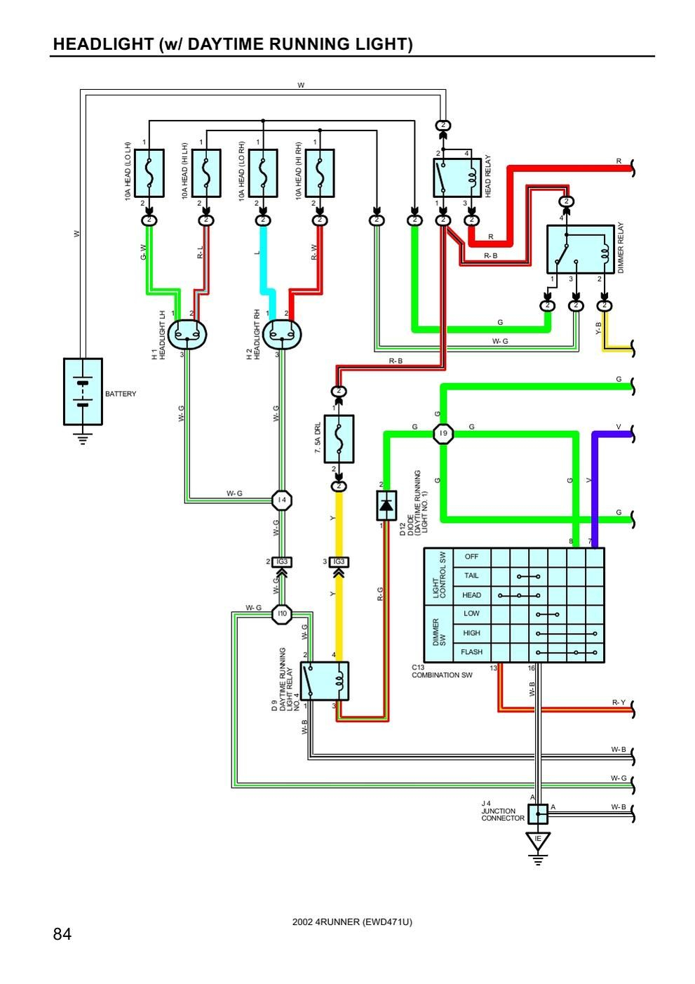
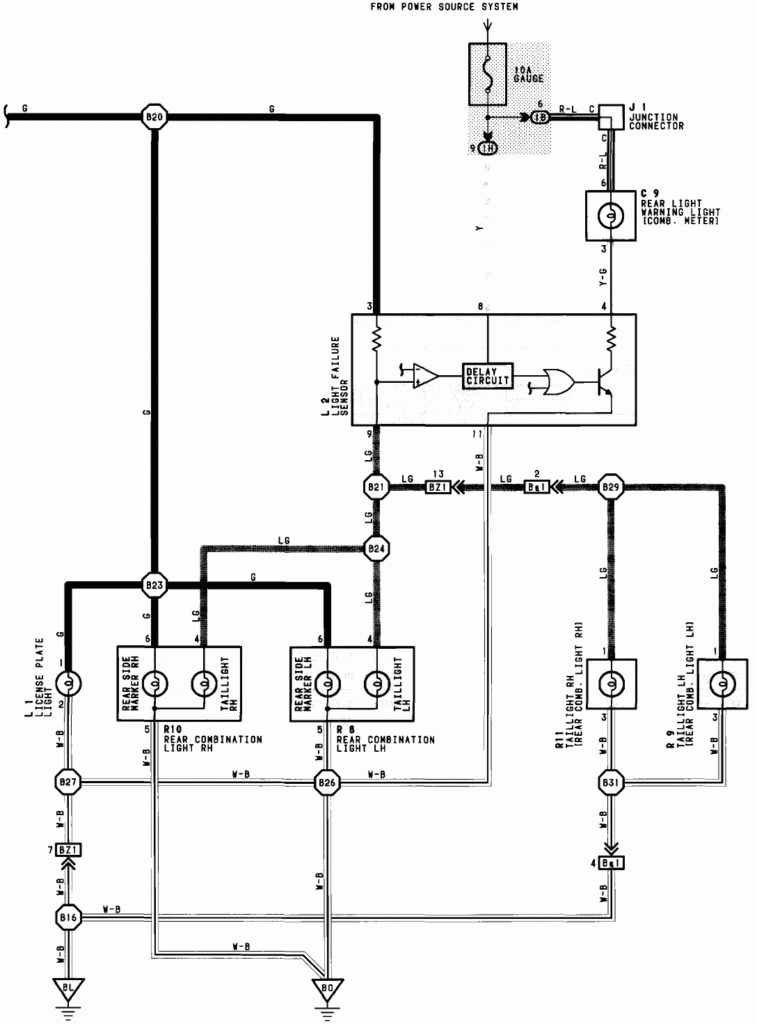
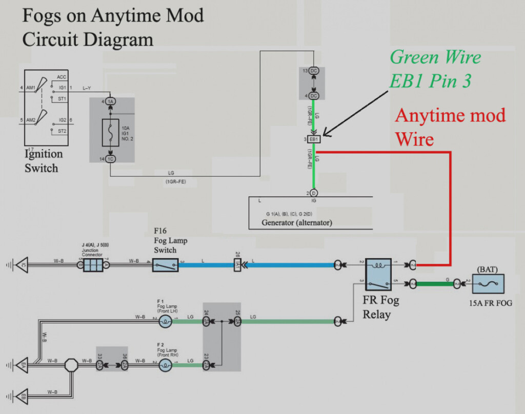
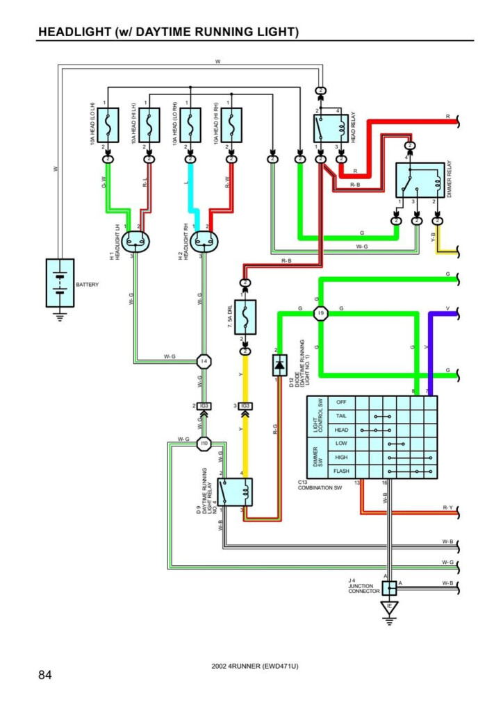
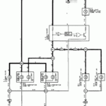
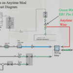
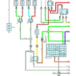
2013 Toyota Tacoma Tail Light Wiring Diagram – A damaged or dysfunctional tail light circuit could possibly be the consequence of interior cabling complications with a single or both back end pods. Cross-wiring when utilizing no-normal lights or aftermarket pods is probably responsible for this. It’s also likely that the wiring to the back end lights was adjusted by a prior manager.
Finding the supply of a electrical wiring dilemma is the first task to dealing with it. Be sure that the region is rust-clean and free. Clean the floor area as necessary, and substitute any rusted floor anchoring screws. After that, seem underneath the floor screw for any much more engagement ring terminals. Try moving the harness’s ground wire to a new spot towards the bottom of the car if this doesn’t fix the issue.
problems with the proper (traveler area) light fixture as well as the still left (motorist side) light fixture
The Toyota lights in the remaining (car owner aspect) and proper (person side) usually are not working properly. You must initially establish the 2 bulbs’ potential options. The right transform sign sign move power the best lamp, whilst the left change transmission indication switch power the kept lamp. The steering column stalk management is connected to the still left switch.
If you suspect a blown fuse, check the fuse. If it is bad, replace the fuse with one of the same amperage and size. Remove the tail light cover to inspect the bulb if the fuse is functioning properly. Some autos have an entry board where the light is just removed.
A loosened link or possibly a inadequate ground are two more widespread brings about. Make use of a examination lighting to attempt to identify the matter. A failed sign system is actually a more possibility. Irregular hyperflashing might be caused by a defective signal model.
architectural schematics for wiring
The electric assistance with your creating is planned and designed using architectural electrical wiring schematics. In addition, they illustrate the locations of changes and lighting effects and also the connections between them. They could furthermore have a legend to help you understand the emblems, in addition to showing the location where the receptacles are.
Typically, electrical circuits are represented graphically in wiring diagrams. They demonstrate the relative sizes and hues from the circuit’s constituent elements. As they illustrate the connections between components, they are also helpful for troubleshooting. These are commonly used in electrical projects to aid staff in locating and resolving issues.
