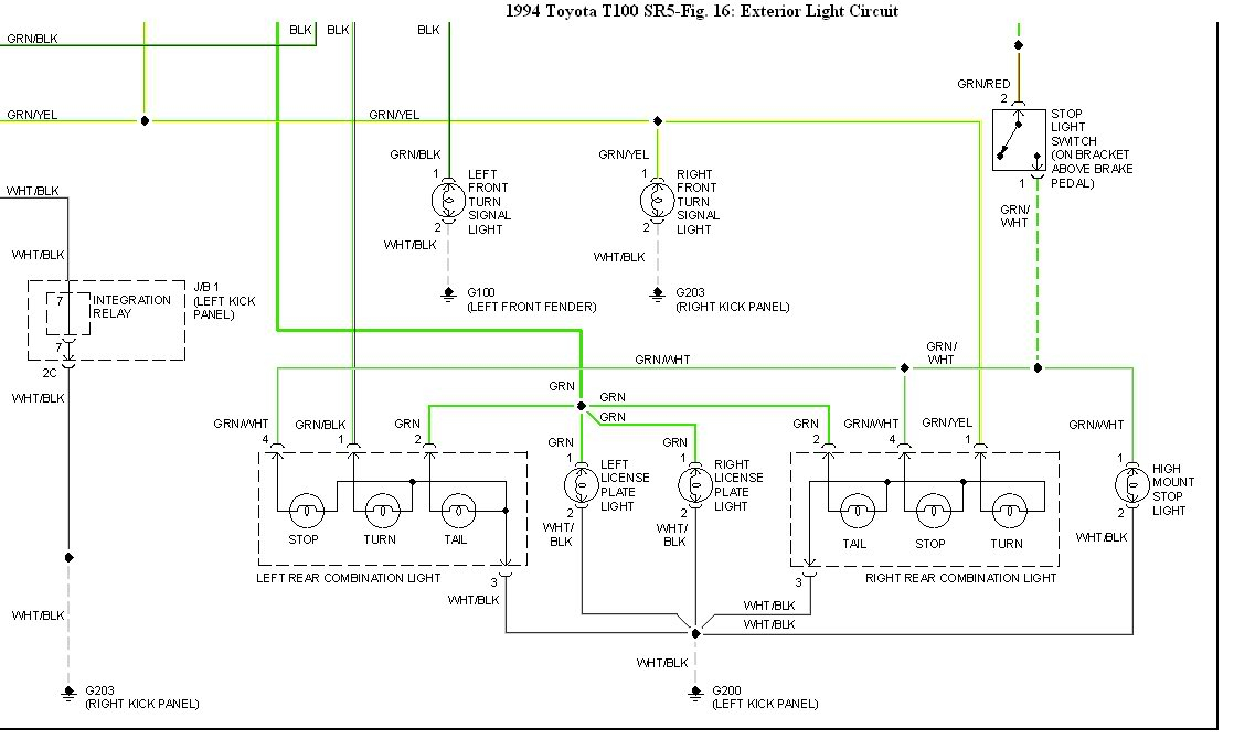
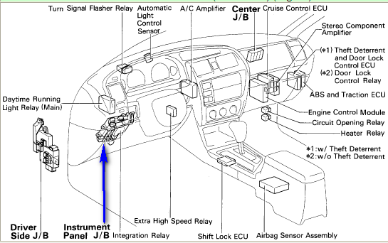
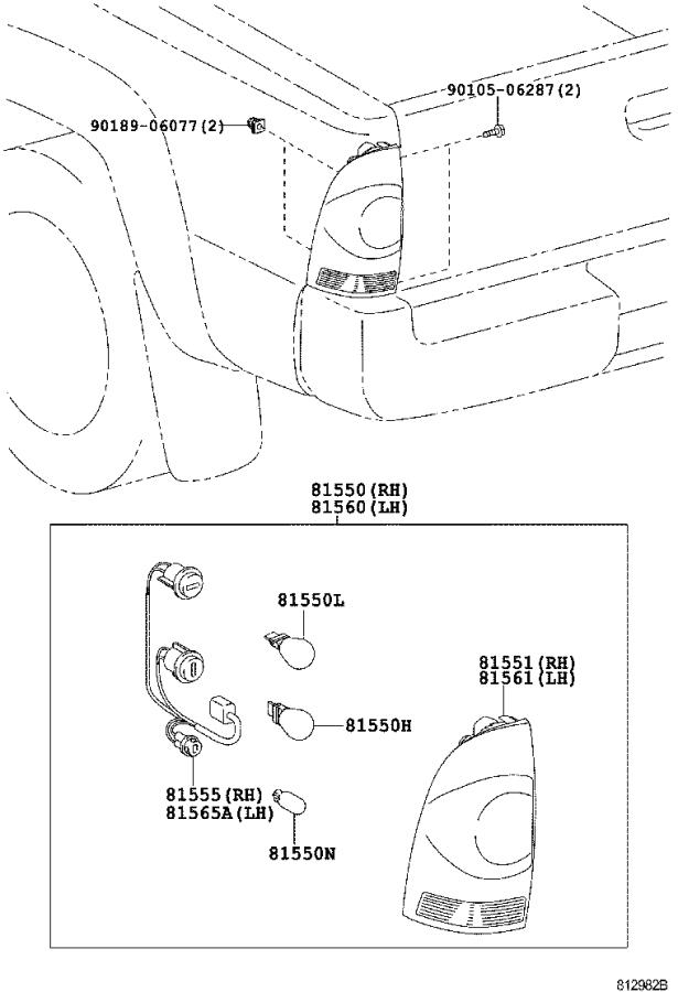
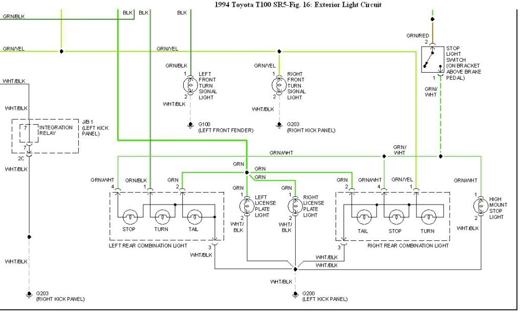
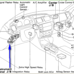
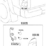
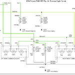
2014 Toyota Tacoma Tail Light Wiring Diagram – A shattered or dysfunctional tail light circuit could possibly be the consequence of interior wires issues with one or each back pods. Cross-wiring when utilizing low-common lamps or aftermarket coffee pods is probably to blame for this. It’s also likely that the cabling for that rear lighting fixtures was adjusted with a before operator.
Seeking the method to obtain a electrical wiring dilemma is the first step toward solving it. Be sure that the region is rust-free and clean. Clear the soil area as required, and substitute any rusted ground anchoring screws. After that, appearance underneath the terrain screw for almost any much more diamond ring terminals. Try moving the harness’s ground wire to a new spot towards the bottom of the car if this doesn’t fix the issue.
complications with the right (traveler side) light fixture along with the left (car owner side) lamp
The Toyota lights on the kept (motorist side) and correct (person part) are not functioning properly. You need to very first determine the two bulbs’ power sources. The best transform transmission sign swap powers the correct light, while the kept convert sign indicator move powers the remaining light. The steering line stalk control is connected to the kept change.
Check the fuse if you suspect a blown fuse. If it is bad, replace the fuse with one of the same amperage and size. If the fuse is functioning properly, remove the tail light cover to inspect the bulb. Some autos come with an gain access to board where the lamp is actually taken out.
A loose interconnection or possibly a bad floor are two more prevalent causes. Utilize a check light-weight to try to determine the issue. A unsuccessful indicator model is actually a more likelihood. Irregular hyperflashing might be due to a faulty signal system.
design schematics for cabling
The electric assistance with your developing is planned and designed employing architectural wiring schematics. Furthermore, they show the locations of switches and lighting and also the contacts between them. They might in addition have a icon to help you read the symbols, as well as exhibiting where the receptacles are.
Typically, electrical circuits are represented graphically in wiring diagrams. They show the family member hues and sizes of the circuit’s constituent components. They are also helpful for troubleshooting, as they illustrate the connections between components. They may be commonly used in electric projects to aid personnel in locating and resolving problems.
