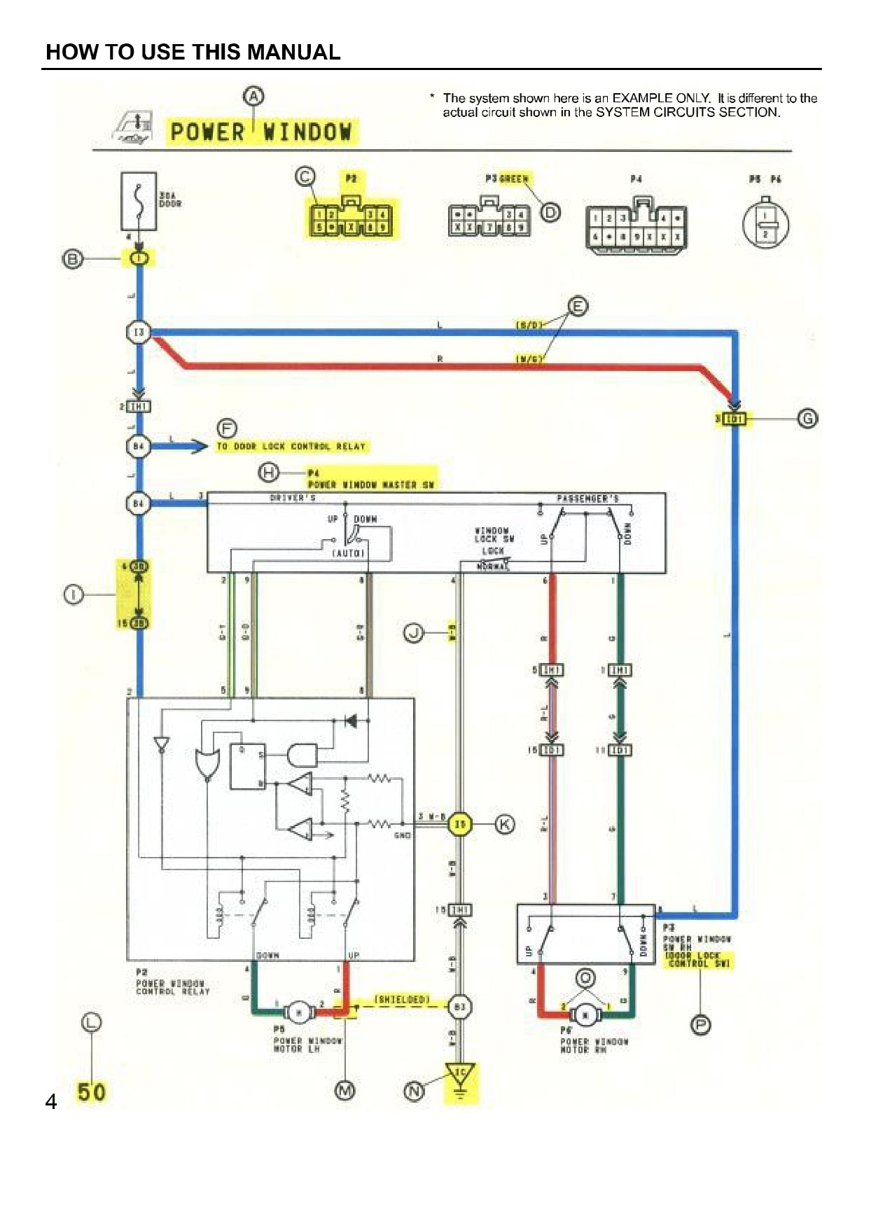
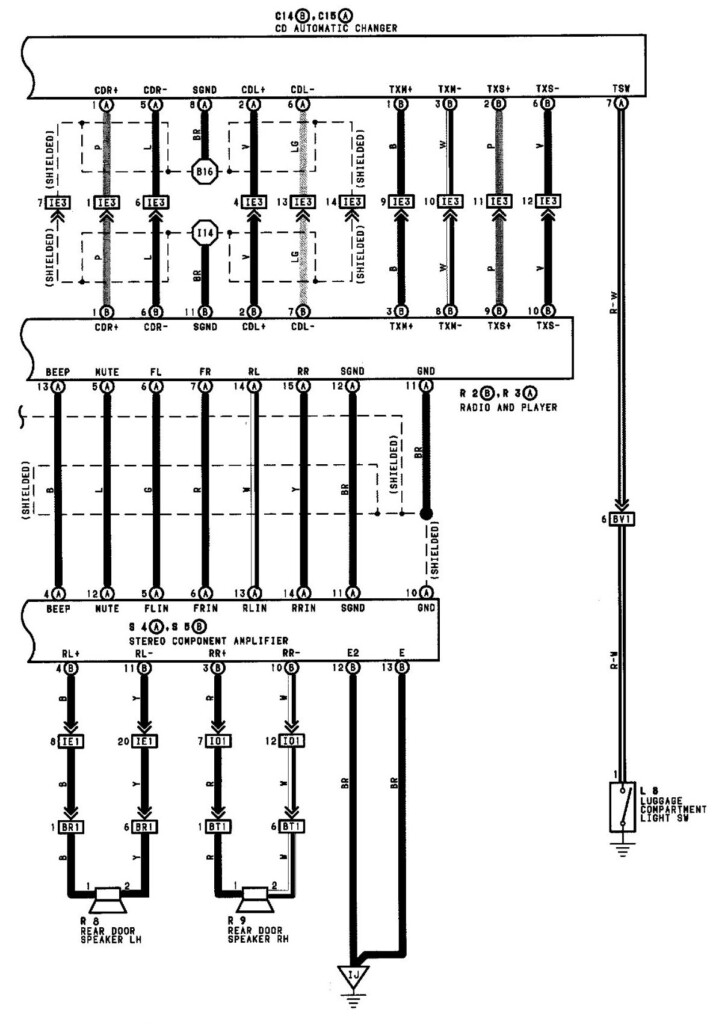
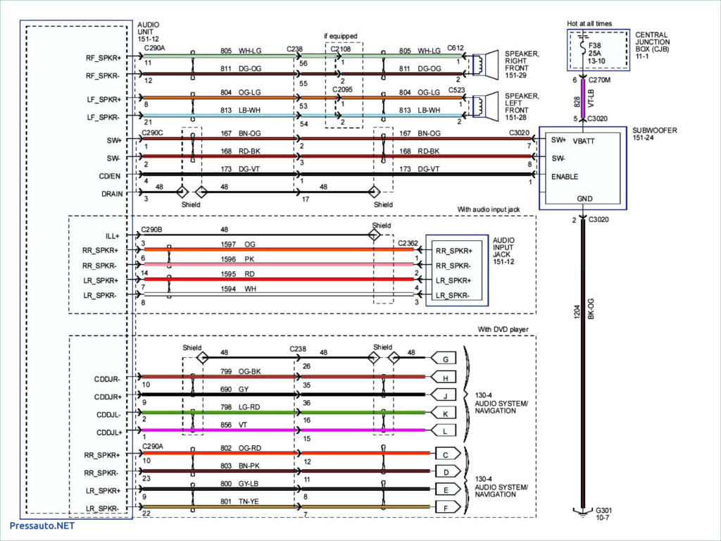
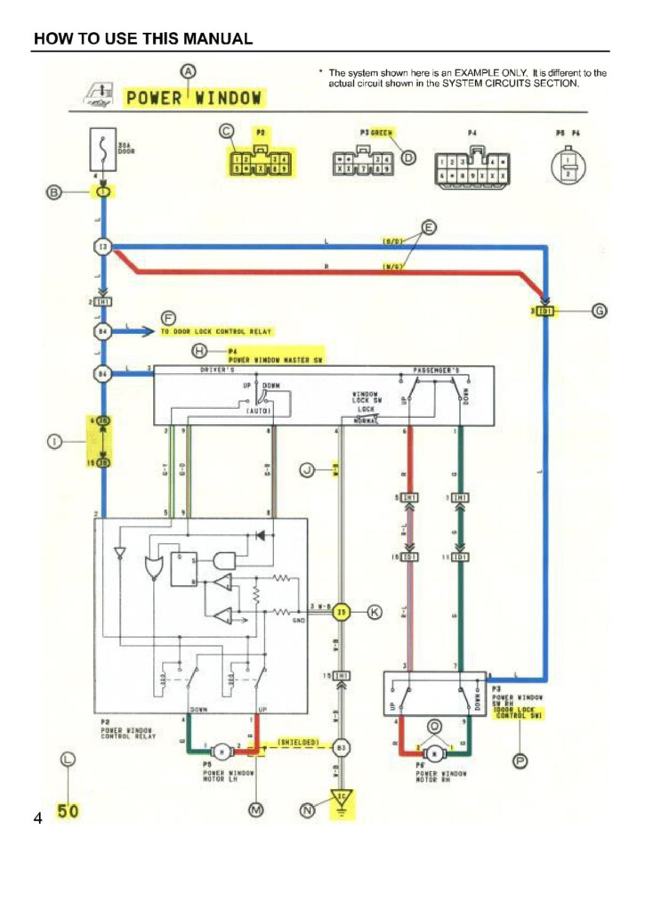
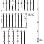
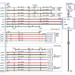
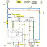
2005 Toyota Camry Electrical Wiring Diagram – The connector code is commonly used to recognize no matter if a connector is female or male. The computer code is additionally used to separate numerous wire utilize styles. The guy terminal interconnection is denoted by the sign (), whilst the men and women connector pin numbers are denoted by phone numbers away from rule.
The links involving numerous pieces are revealed from the cabling diagram. A link computer code can be .5 or .3 mm, for instance. In addition stated is the cable’s colour program code.
The pin quantities of the two female and male connections are suggested by numbers on the exterior of connector codes.
The wire and locations routings of your wiring harness are exhibited inside a electrical wiring diagram. The 1st notice from the link computer code designates in which the connector is on the diagram. An earth level can also be included in the schematic, which helps with determining where connector needs to be placed. As well as the planet installation roles, the cabling diagram will likely show the connectors and connector phone numbers that correspond to the same portion.
The wiring connector is not linked if there is no code. A shattered line furthermore ensures that both the connections are the same. It’s crucial that you take a look at a electrical wiring diagram carefully to help you right away determine the right connector.
Ground no
The electric powered connection between a substantial part along with the earth is called the ground stage. In the Toyota electrical cabling schematic, the ground stage program code is displayed by a message plus a variety. The amount denotes the earth point’s serial quantity, whilst the letter denotes the alphabetical program code to the cable harness. The ground level rule also displays where the ignition key and cable splice position are placed.
It helps to understand the different circuits in the car before starting to diagnose an electrical problem. A cabling diagram demonstrates the specific cabling of each and every circuit, that is divided into various circuits for every single system inside a vehicle. It is very important to understand how every circuit characteristics along with the floor position that hooks up it.
prohibit connectors for relays
In the remaining part of the car’s tool panel are the relay prevent connectors. They become a member of J/B No.3 for the Musical instrument Board Cable (IW). 3 heroes make up the program code around the relay obstruct connectors, each of which stands for the cabling or program. Additionally, it will say if the connector is male or female.
The diagram also demonstrates the hue program code for that communicate prevent connector. The cable’s shade computer code is proven in parenthesis with this diagram. Blue would be the coloration designation for girl connectors.
coded colours
Toyota electric powered cabling diagrams are coloration coded to help make diagnosis and problem solving less complicated. The related color rules make it easier to determine the proper connection between various auto pieces. A wiring harness for Toyota automobiles involves several wires, including positive and negative, terrain, and/reduced voltage cords. You should pay attention to the green/white and green/reddish colored colors from the wires schematic when looking at it since they represent the remaining convert transmission as well as the brake lamps, correspondingly.
A Toyota Electric Wires Diagram with red arrows signifies that the connectors would be the correct sizing. But look out for the yellow arrows. They are not a reliable measure of the proper dimension. They might perplex you.
Toyota electric electrical wiring diagram problem solving
Being familiar with your Toyota’s power cabling is crucial, particularly the color rules. Around the world defined Toyota cabling shade rules may well help with a quick diagnosis of electric powered problems. Because Toyota automobiles feature a large number of sensors and electrical components, it is crucial to comprehend the wiring diagram’s color codes.
The contacts between considerable ground and components points are displayed on the cabling diagram. The Tool Board Wire is connected to the Generator Place Main Wire from the “Ch1” connector (women). In the left kick board, there exists a connector. The center of the rear solar panel is the place where the “H2” terrain level is located. The bond involving these areas and the other substantial factors is discussed by the circuit diagram. Verify the connections to make sure that each aspect is linked to the correct soil.
