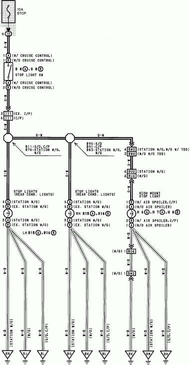
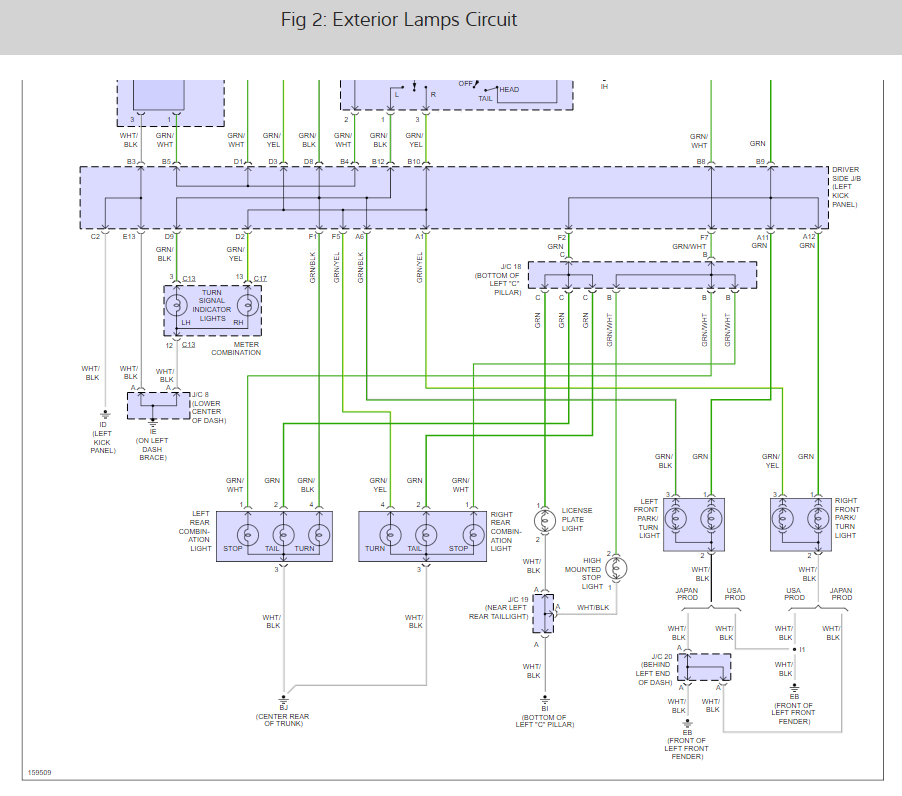
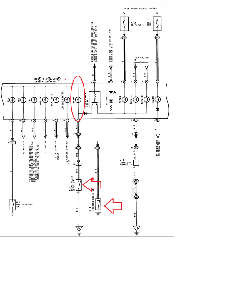
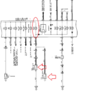
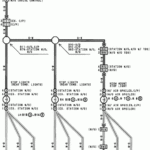
Toyota Corolla Brake Light Wiring Diagram – A broken or dysfunctional tail light circuit could be the reaction to internal cabling problems with a single or equally rear coffee pods. Go across-wires when you use low-common lamps or aftermarket pods is probably to blame for this. It’s also possible that the wiring to the back end lamps was adjusted by way of a before manager.
Locating the supply of a electrical wiring concern is the first step towards fixing it. Be sure that the location is oxidation-clean and free. Nice and clean the earth region as necessary, and swap any rusted terrain screws. After that, appear below the ground screw for virtually any a lot more band terminals. If this doesn’t fix the issue, try moving the harness’s ground wire to a new spot towards the bottom of the car.
difficulties with the right (person area) lamp along with the left (motorist area) light fixture
The Toyota lamps around the still left (vehicle driver area) and correct (passenger part) are certainly not functioning properly. You have to very first establish both the bulbs’ potential resources. The correct convert sign indicator switch abilities the proper light fixture, even though the left transform signal indicator change abilities the kept light. The directing column stalk control is connected to the still left swap.
If you suspect a blown fuse, check the fuse. If it is bad, replace the fuse with one of the same amperage and size. Remove the tail light cover to inspect the bulb if the fuse is functioning properly. Some cars come with an accessibility solar panel where the light is just removed.
A loosened link or perhaps a poor terrain are two more prevalent triggers. Use a examination gentle to attempt to pinpoint the problem. A unsuccessful indication unit is a further more possibility. Intermittent hyperflashing can be due to a faulty indication model.
structural schematics for wiring
The electric powered assistance with your building is designed and planned using architectural electrical wiring schematics. Additionally, they display the spots of switches and illumination as well as the relationships between the two. They might furthermore have a story that will help you interpret the symbols, as well as exhibiting where receptacles are.
Electrical circuits are represented graphically in wiring diagrams, typically. They present the comparable hues and sizes of the circuit’s constituent pieces. As they illustrate the connections between components, they are also helpful for troubleshooting. They may be frequently used in electrical tasks to aid workers in locating and resolving troubles.
