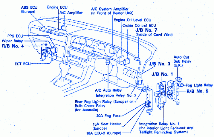
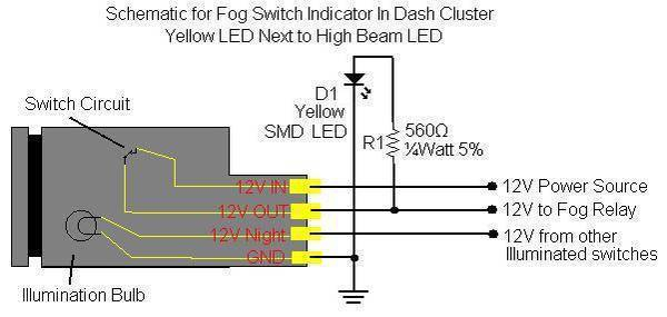
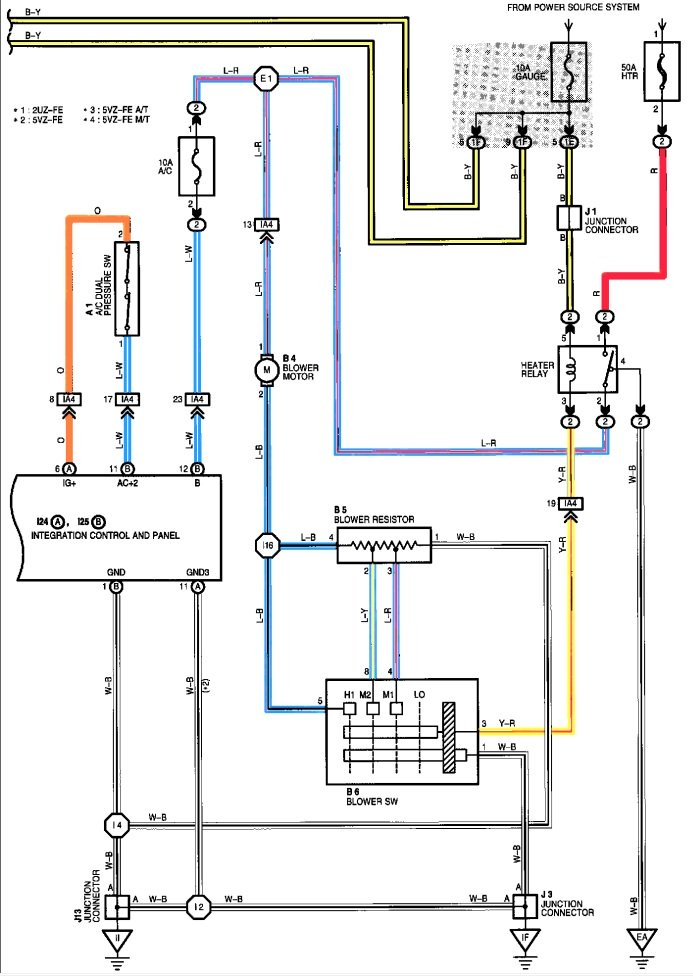
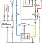
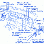
2000 Toyota Tundra Fog Light Wiring Diagram – A damaged or dysfunctional tail light circuit can be the consequence of inner wiring difficulties with 1 or equally rear pods. Cross-wiring when utilizing non-standard lamps or upgraded coffee pods is most probably to blame for this. It’s also probable that the electrical wiring to the rear lamps was adjusted by way of a preceding manager.
Seeking the way to obtain a wiring concern is the first task towards fixing it. Be sure that the region is rust-free and clean. Nice and clean the ground area as necessary, and swap any rusted terrain screws. After that, seem beneath the soil screw for almost any more engagement ring terminals. If this doesn’t fix the issue, try moving the harness’s ground wire to a new spot towards the bottom of the car.
issues with the right (traveler aspect) lamp and also the left (vehicle driver area) light fixture
The Toyota lights on the kept (car owner aspect) and correct (person aspect) will not be working correctly. You have to initial assess the 2 bulbs’ power sources. The right turn transmission indication swap powers the correct light, as the still left transform signal signal move power the left lamp. The steering line stalk control is linked to the remaining swap.
Check the fuse if you suspect a blown fuse. If it is bad, replace the fuse with one of the same amperage and size. Remove the tail light cover to inspect the bulb if the fuse is functioning properly. Some autos provide an access board where light is just taken out.
A loose relationship or possibly a poor soil are two more widespread leads to. Make use of a test lighting to try to identify the issue. A was unsuccessful sign device is really a further more possibility. Intermittent hyperflashing can be caused by a faulty sign model.
design schematics for cabling
The electric support inside your building is planned and designed making use of architectural electrical wiring schematics. Moreover, they display the areas of switches and illumination along with the contacts between them. They might in addition have a legend that will help you read the icons, and also displaying the location where the receptacles are.
Electrical circuits are represented graphically in wiring diagrams, typically. They demonstrate the general hues and sizes from the circuit’s constituent parts. As they illustrate the connections between components, they are also helpful for troubleshooting. They can be commonly used in power jobs to assist employees in resolving and locating troubles.
