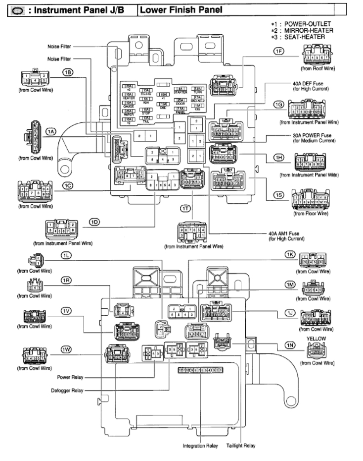
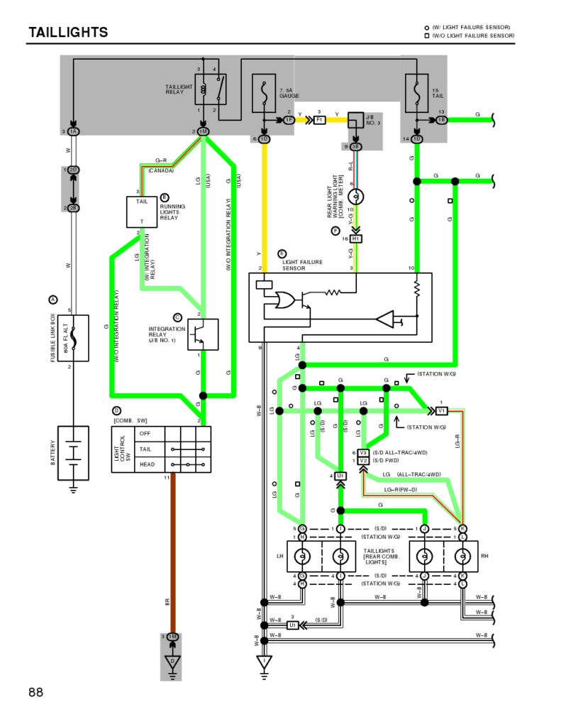
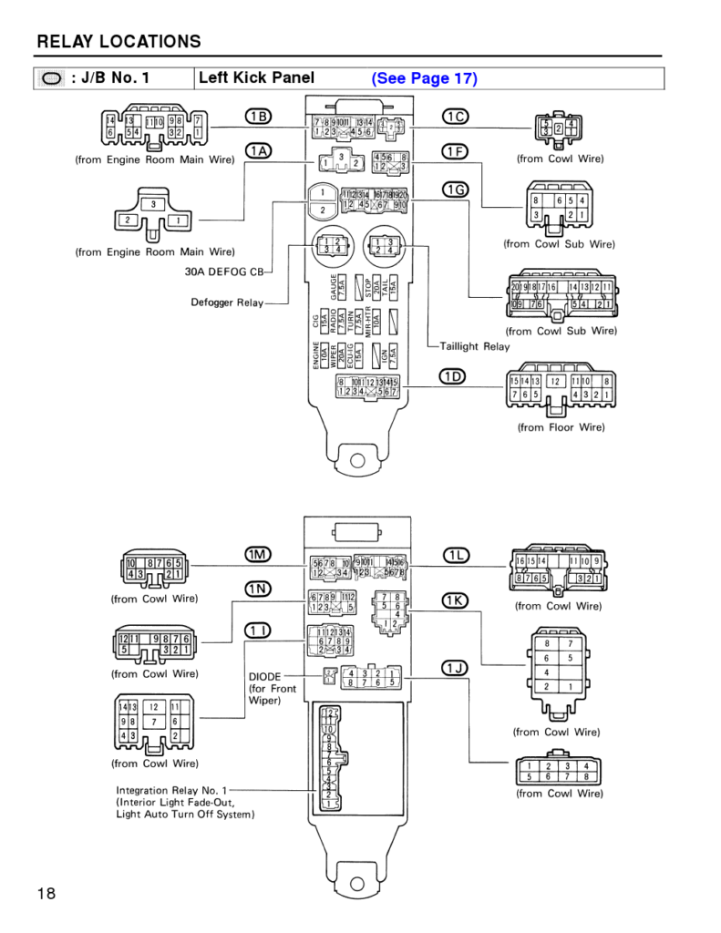
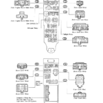
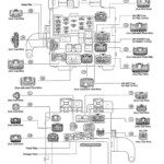
1989 Toyota Camry Light Wiring Diagram – A shattered or dysfunctional tail light-weight circuit can be the consequence of interior cabling complications with 1 or both back end pods. Cross-electrical wiring when utilizing low-regular lights or upgraded pods is probably to blame for this. It’s also possible that the cabling for that back end lighting fixtures was modified with a before operator.
Locating the way to obtain a cabling concern is the first step in the direction of resolving it. Ensure that the area is rust-free and clean. Nice and clean the floor region as necessary, and replace any rusted floor screws. Next, appearance below the ground screw for just about any a lot more engagement ring terminals. If this doesn’t fix the issue, try moving the harness’s ground wire to a new spot towards the bottom of the car.
issues with the best (person area) light fixture as well as the kept (motorist part) lamp
The Toyota lighting fixtures on the left (vehicle driver aspect) and right (passenger part) are certainly not working correctly. You should initial assess both bulbs’ strength sources. The right turn sign indication switch power the proper light fixture, while the left convert transmission signal move abilities the left light. The steering column stalk management is linked to the remaining swap.
If you suspect a blown fuse, check the fuse. If it is bad, replace the fuse with one of the same amperage and size. If the fuse is functioning properly, remove the tail light cover to inspect the bulb. Some autos come with an access solar panel where the light bulb is actually eliminated.
A reduce relationship or possibly a very poor soil are two more widespread brings about. Make use of a test gentle to try to identify the matter. A unsuccessful sign model is actually a additional chance. Irregular hyperflashing might be brought on by a flawed signal model.
structural schematics for wires
The electric service within your constructing is planned and designed using design wires schematics. Additionally, they show the spots of changes and illumination and also the connections between them. They can in addition have a story that will help you interpret the symbols, in addition to demonstrating where the receptacles are.
Typically, electrical circuits are represented graphically in wiring diagrams. They show the comparable hues and sizes of the circuit’s constituent pieces. They are also helpful for troubleshooting, as they illustrate the connections between components. They are frequently used in electrical assignments to aid employees in locating and resolving issues.
