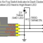
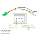
2007 Toyota Tacoma Fog Lights Wiring Diagram – A damaged or dysfunctional tail gentle circuit can be the reaction to interior cabling issues with 1 or equally rear pods. Go across-wires when you use no-regular lights or upgraded pods is probably responsible for this. It’s also likely that the electrical wiring to the back lighting fixtures was altered from a previous proprietor.
Locating the source of a cabling concern is step one to dealing with it. Be sure that the location is rust-free and clean. Clear the floor area as essential, and swap any rusted soil screws. Next, look beneath the ground attach for just about any a lot more ring terminals. If this doesn’t fix the issue, try moving the harness’s ground wire to a new spot towards the bottom of the car.
problems with the right (passenger aspect) light and the kept (driver part) light fixture
The Toyota lighting fixtures around the kept (vehicle driver side) and correct (traveler part) are certainly not working properly. You should first determine the 2 bulbs’ strength places. The best transform signal indication move capabilities the right lamp, whilst the remaining transform transmission signal swap abilities the kept light fixture. The directing column stalk handle is linked to the remaining move.
If you suspect a blown fuse, check the fuse. If it is bad, replace the fuse with one of the same amperage and size. Remove the tail light cover to inspect the bulb if the fuse is functioning properly. Some autos have an accessibility solar panel in which the light is simply removed.
A reduce link or even a very poor floor are two more widespread causes. Make use of a examination lighting to try to determine the problem. A was unsuccessful indicator model is a additional probability. Sporadic hyperflashing may be due to a flawed sign device.
structural schematics for wiring
The electrical assistance with your constructing is designed and planned employing architectural cabling schematics. Additionally, they demonstrate the locations of switches and illumination plus the links between them. They may in addition have a icon to help you interpret the icons, in addition to demonstrating where receptacles are.
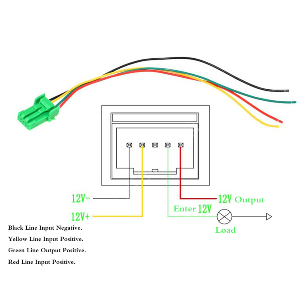
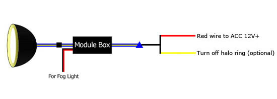
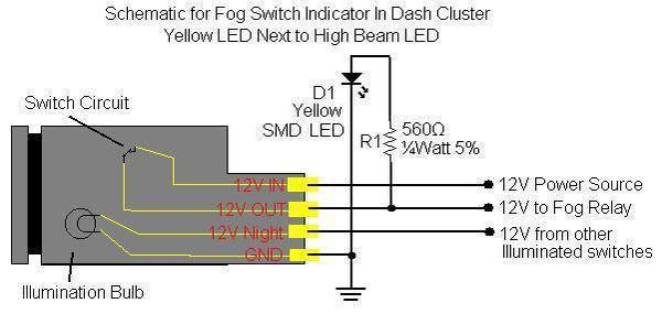
Electrical circuits are represented graphically in wiring diagrams, typically. They present the comparable hues and sizes of the circuit’s constituent pieces. As they illustrate the connections between components, they are also helpful for troubleshooting. These are frequently used in electric powered projects to support personnel in resolving and locating concerns.
