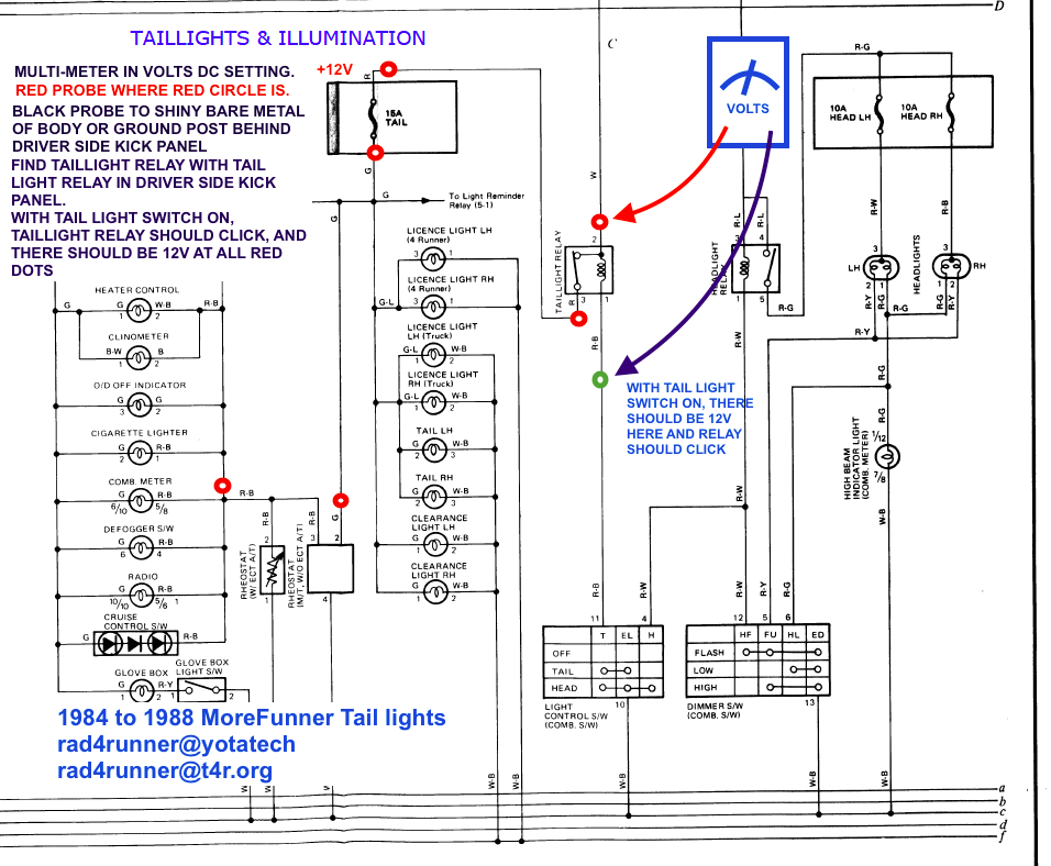
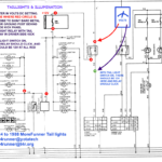
Toyota T100 Tail Light Wiring Diagram – A shattered or dysfunctional tail light circuit can be the result of interior wires issues with one particular or the two back coffee pods. Go across-cabling when you use no-regular bulbs or upgraded coffee pods is likely to blame for this. It’s also entirely possible that the wiring for that back lighting fixtures was adjusted by a prior operator.
Locating the supply of a wiring problem is the first task toward fixing it. Be sure that the region is oxidation-clean and free. Nice and clean the soil location as necessary, and replace any rusted terrain screws. Next, appear underneath the terrain screw for virtually any a lot more ring terminals. If this doesn’t fix the issue, try moving the harness’s ground wire to a new spot towards the bottom of the car.
problems with the correct (person aspect) lamp along with the remaining (vehicle driver area) lamp
The Toyota lamps on the left (car owner side) and right (person side) usually are not functioning properly. You must initially determine the two bulbs’ power places. The right change transmission indicator swap abilities the correct lamp, even though the left turn sign signal swap capabilities the kept lamp. The steering line stalk control is linked to the left switch.
Check the fuse if you suspect a blown fuse. If it is bad, replace the fuse with one of the same amperage and size. If the fuse is functioning properly, remove the tail light cover to inspect the bulb. Some cars offer an accessibility panel in which the bulb is simply taken away.
A reduce connection or a inadequate floor are two more widespread causes. Work with a analyze light-weight to try to pinpoint the matter. A was unsuccessful indication model is actually a further more likelihood. Sporadic hyperflashing might be brought on by a faulty indicator system.
structural schematics for wires
The electrical services within your building is designed and planned making use of design electrical wiring schematics. In addition, they show the locations of switches and illumination and also the relationships between the two. They can also have a icon to help you understand the icons, and also displaying where receptacles are.
Electrical circuits are represented graphically in wiring diagrams, typically. They demonstrate the general hues and sizes from the circuit’s constituent components. As they illustrate the connections between components, they are also helpful for troubleshooting. They can be commonly used in power assignments to assist workers in locating and resolving troubles.
