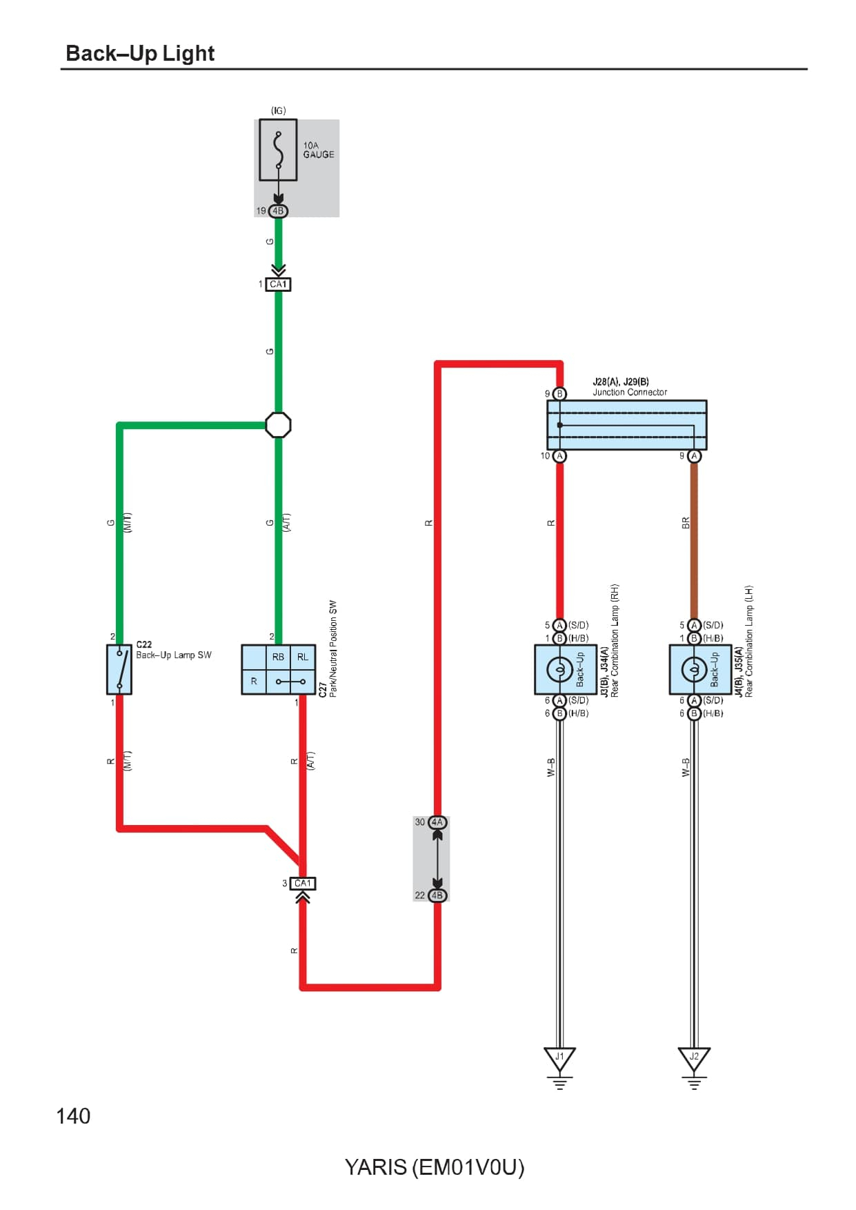
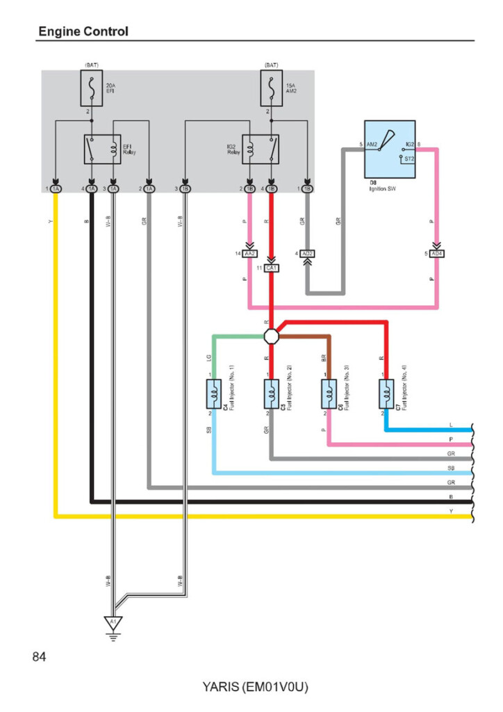
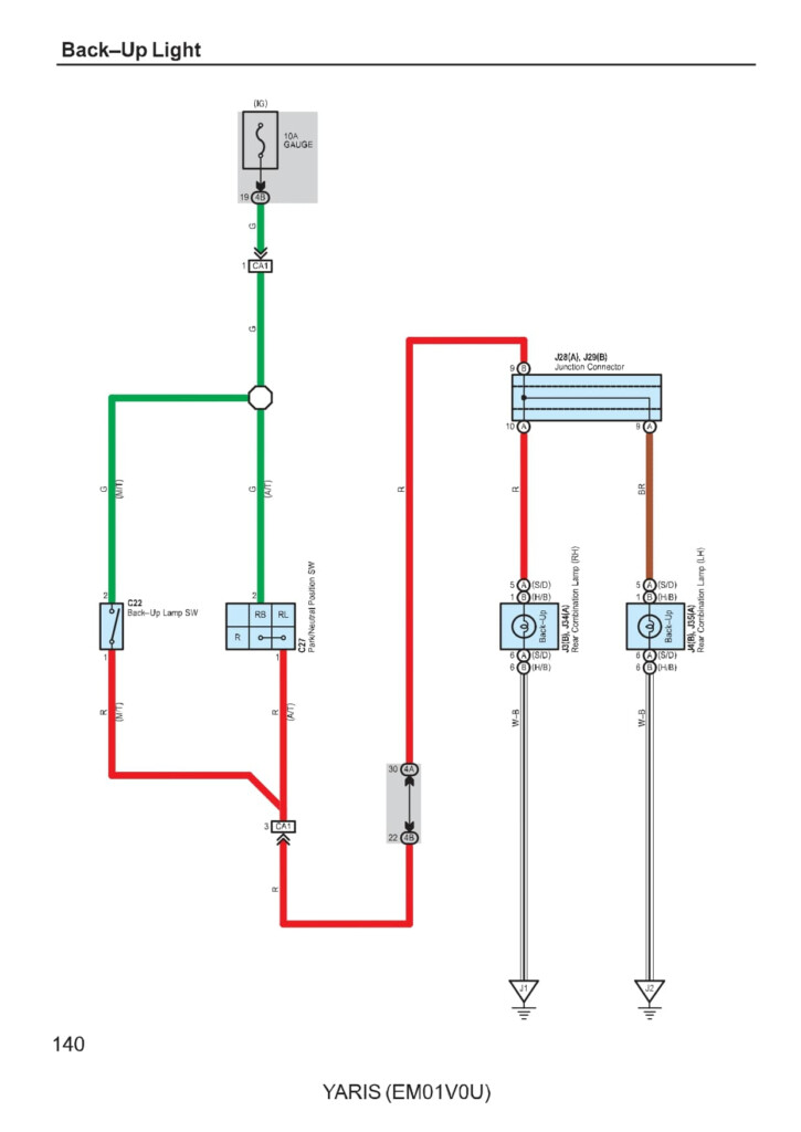
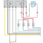
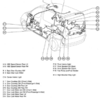
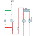
Toyota Yaris 2001 Electrical Wiring Diagram – The connector rule is commonly used to distinguish whether or not a connector is female or male. The rule is also accustomed to distinguish between a variety of wire harness configurations. The men terminal relationship is denoted from the sign (), while the female and male connector pin numbers are denoted by figures outside the code.
The links among numerous elements are exhibited by the cabling diagram. A connection rule may be .5 or .3 mm, as an example. In addition stated may be the cable’s shade rule.
The pin numbers of equally male and female connectors are indicated by amounts on the outside of connector rules.
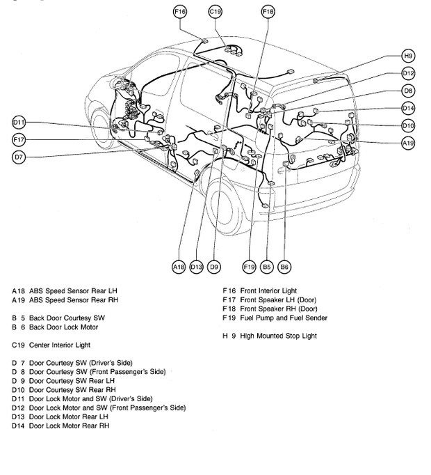
The locations and wire routings of a electrical wiring control are showcased in a wires diagram. The initial note from the interconnection program code designates the location where the connector is on the diagram. An earth level is additionally included around the schematic, which assists in deciding the location where the connector must be positioned. Together with planet installing positions, the wiring diagram will also show the connectors and connector figures that match a similar portion.
If there is no code, the wiring connector is not linked. A broken line furthermore suggests that the 2 connections are the exact same. It’s important to look at a wires diagram attentively to help you immediately identify the proper connector.
Ground absolutely no
The electrical connection between an important part and the earth is called the soil level. In the Toyota electrical wires schematic, the earth level computer code is depicted by a notice along with a quantity. The quantity denotes the floor point’s serial quantity, as the notice denotes the alphabetical computer code for your wire control. The earth level program code also displays the location where the ignition important and cable splice position are placed.
Before starting to diagnose an electrical problem, it helps to understand the different circuits in the car. A wires diagram demonstrates the exact wiring for each circuit, that is divided into various circuits for each and every system in a car. It is very important to comprehend how each and every circuit characteristics along with the soil position that connects it.
prevent connections for relays
Around the still left part of the car’s device solar panel will be the communicate block connections. They become a member of J/B No.3 to the Device Panel Cable (IW). About three heroes constitute the program code about the relay prohibit connectors, each of which holders for the electrical wiring or system. Additionally, it will say if the connector is male or female.
The diagram also shows colour computer code for your relay block connector. The cable’s color program code is proven in parenthesis in this diagram. Blue would be the colour designation for girl connectors.
coded colors
Toyota electronic wiring diagrams are coloration coded to create diagnosis and problem solving easier. The corresponding shade rules help you to figure out the correct connection between numerous vehicle pieces. A cabling control for Toyota vehicles consists of numerous wires, which includes good and bad, terrain, and high/lower voltage cords. You should pay attention to the environmentally friendly/white and green/red-colored colours inside the wires schematic when reading through it since they stand for the kept change indicate as well as the brake lights, respectively.
A Toyota Electric Wiring Diagram with red arrows signifies that the connectors will be the proper dimensions. But be cautious about the discolored arrows. They are certainly not a reliable measure in the appropriate sizing. They may perplex you.
Toyota electric powered wires diagram troubleshooting
Comprehending your Toyota’s power wires is very important, in particular the color codes. Throughout the world defined Toyota electrical wiring color rules may possibly assist in a quick proper diagnosis of power concerns. Because Toyota automobiles feature a large number of sensors and electrical components, it is crucial to comprehend the wiring diagram’s color codes.
The links involving important components and ground factors are shown on the cabling diagram. The Musical instrument Solar panel Wire is coupled to the Motor Room Primary Cable from the “Ch1” connector (girl). Around the left strike board, there exists a connector. The centre of the back solar panel is the place where the “H2” terrain stage is found. The bond among these areas and also the other important factors is revealed by the circuit diagram. Authenticate the contacts to make certain that each and every part is connected to the correct ground.
